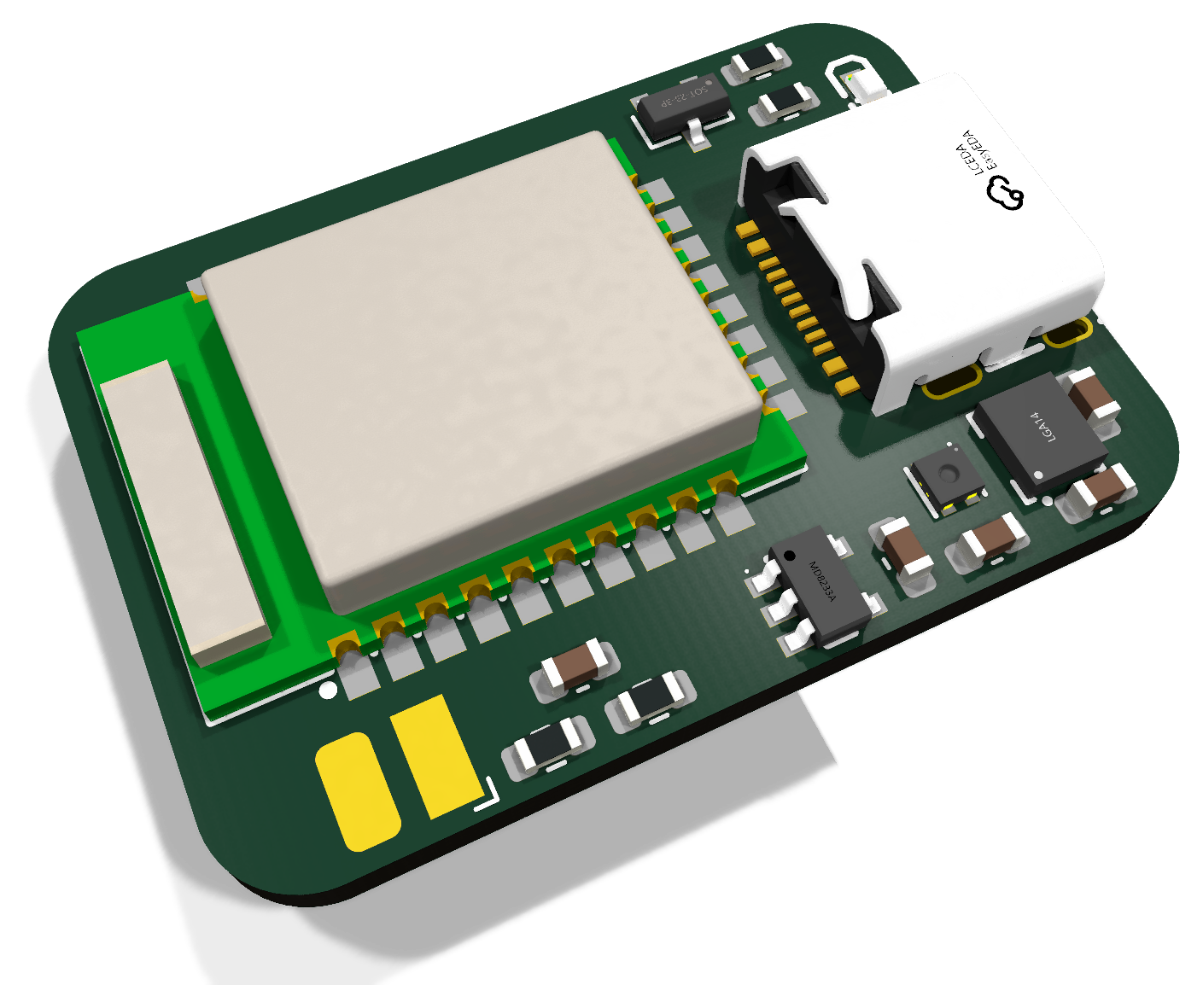
The first prototype showed that the impedance measurement works on the bench and on an arm. The second prototype turns that circuit into a board that can fit inside a wearable.
We replaced the ESP32-C6 development module with an E73 nRF52840 module. It includes Bluetooth, USB and an antenna, so we do not need to design the radio section from scratch. It can also run directly from the LiPo battery.
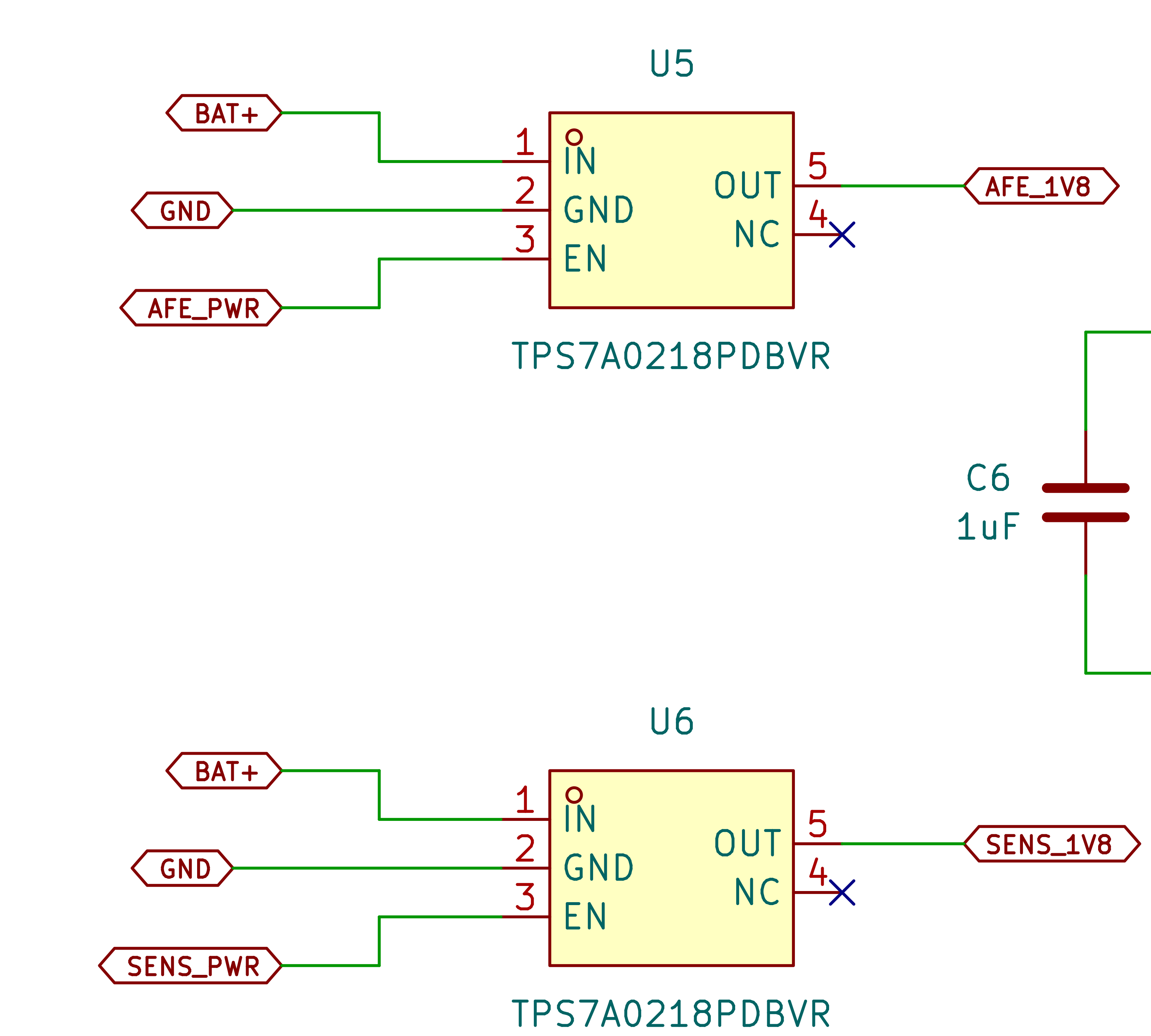
Two supplies that can switch off
The MAX30001 and its clock use one 1.8 V supply. The motion and humidity sensors use another. The controller can switch each supply separately, which means most of the board can be off between measurements.
This also affects the signal connections. A powered controller must not send current into a sensor that has been switched off. The pull-up resistors and clock supplies are connected to the same power domain as the parts they serve.
Motion and humidity
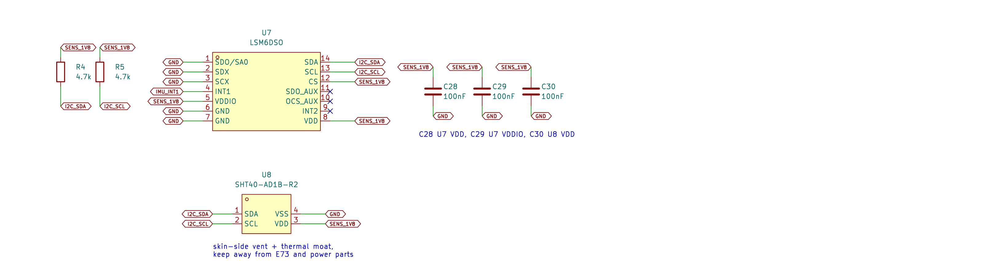
Arm movement changes a bioimpedance reading. The LSM6DSO motion sensor will let us mark measurements taken during movement and check whether the band is being worn. The SHT40 measures temperature and humidity under the band, which helps us spot changes caused by sweat or a shifted strap.
The humidity sensor needs a small opening toward the skin and should be kept away from warm components. That affects both the PCB layout and the enclosure.
Choices for this board
| Decision | Reason |
|---|---|
| Keep USB-C | One connector handles charging, programming and the serial console. |
| Start with a 200 mAh battery | It fits the first enclosure and gives us enough time between charges during testing. |
| Use a simple LED | The addressable LED on the first board used too much power when idle. |
| Add ECG connections | The same inner electrodes can be connected to the ECG input for later tests. |
Current status
The schematic is complete and the layout is under way. Placement and most of the routing are done, but the board is not finished: some connections are still open and the design rule check still reports problems to work through.
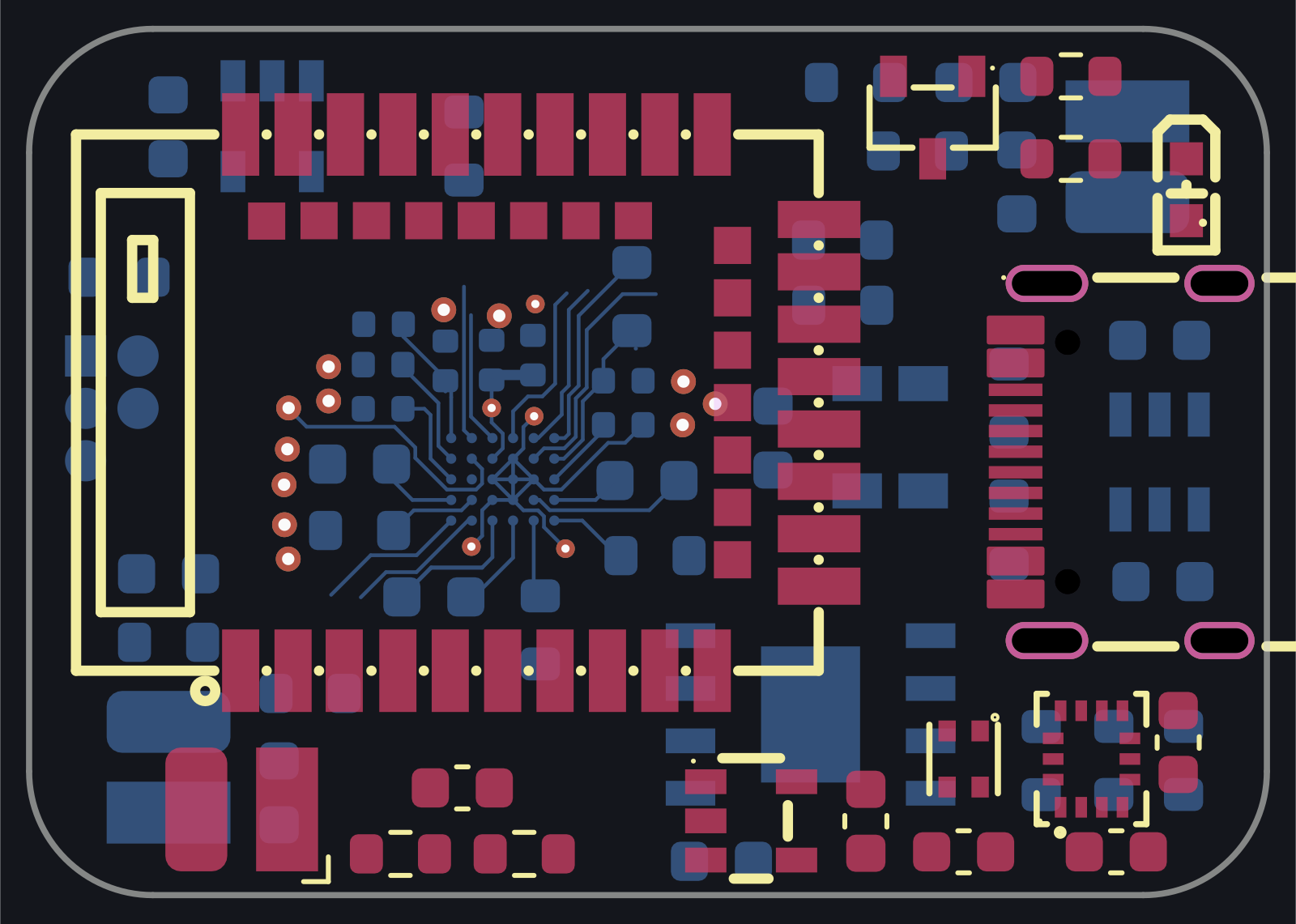
Everything has to fit into roughly 30 × 21 mm: the controller and its antenna clearance, the skin-side opening for the humidity sensor, the battery, USB-C, the electrode connections and the debug pads.